- 您现在的位置:买卖IC网 > Sheet目录395 > ATAKSTK511-3 (Atmel)KIT RF MODULE 315MHZ FOR STK500
�� �
�
�Getting� Started�
�1.� Once� the� hardware� is� setup,� verify� that� the� DATA� selector� switch� is� in� the� STK511� position.�
�2.� Apply� power,� locate� the� DIP� switch� corresponding� to� the� OPMODE� register,� and� set� the� 5th� DIP�
�switch� to� the� ON� position.� The� LED� enclosed� in� the� silkscreen� legend� labeled� Mod� should� light� up,�
�indicating� a� 1� (corresponding� to� ASK� mode)� was� selected.�
�3.� Press� the� Configure� button� to� program� the� OPMODE� and� LIMIT� registers� with� the� selected�
�configuration.�
�Now,� the� receiver� is� ready� to� receive� an� ASK� (or� in� most� cases,� On-Off� Keyed� -� OOK)� signal.� The�
�demodulated� signal� appears� on� the� DATA� line� of� the� Receiver� Application� Board.� This� signal� can� be�
�routed� to� the� on-board� microcontroller� or� to� the� STK500,� depending� on� the� position� of� the� DATA� selector�
�switch� and� values� of� jumpers� R25-R32� (� See� “Receive� Signal� Routing� ”� on� page� 4-6.� for� additional�
�information).�
�2.3�
�2.3.1�
�Running� the� Demo�
�The� Transmitter� Application� Board� contained� in� the� evaluation� kit� is� shipped� preprogrammed� with� a� light�
�intensity� sensor� program.� It� can� be� used� with� the� STK500/511� Assembly� to� display� ambient� light� inten-�
�sity� using� LEDs� on� the� STK500.� To� run� this� demo� it� must� first� be� properly� configured.�
�STK500� Configuration�
�1.� Insert� an� AT90S8515� microcontroller� into� the� red� 40-pin� socket� (SCKT3000D3)� on� the� STK500�
�board.�
�2.� Verify� that� the� 6-pin� ribbon� cable� is� connected� between� the� SPROG3� and� the� ISP6PIN� headers� and�
�is� oriented� correctly.�
�3.� Connect� the� 10-pin� ribbon� cable� from� the� LEDS� header� to� the� PORTC� header.�
�4.� Apply� power� (12� V)� to� the� supplied� connector� and� turn� on� the� STK500� power� switch.�
�5.� Connect� the� serial� cable� between� RS232� CTRL� and� the� host� PC.�
�6.� In� AVR� Studio,� select� Tools/STK500� from� the� menu.�
�7.� Select� the� Board� tab� and� verify� that� the� VTARGET� voltage� is� set� to� 5� V.�
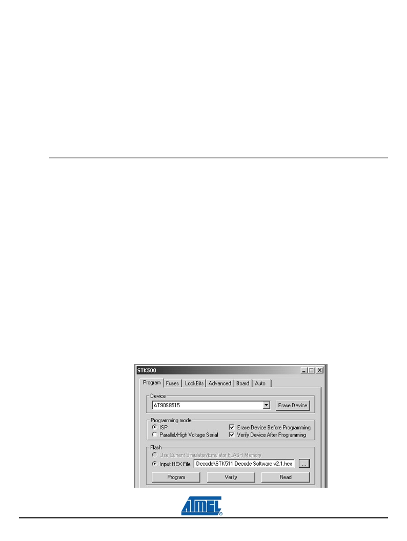
�8.� On� the� Program� tab� ,� select� AT90S8515� from� the� Device� pull-down� menu.�
�9.� Load� the� STK511� RX� Decode.hex� file,� included� on� the� Sample� Software� CD,� into� the� field� labeled�
�Flash� Input� Hex� File� and� press� the� Program� button� (see� Figure� 2-1� on� page� 2-2� ).�
�2-2�
�4842B–AVR–10/09�
�Figure� 2-1.�
�Receiver� Decode� Software�
�STK511� User� Guide�
�发布紧急采购,3分钟左右您将得到回复。
相关PDF资料
ATAKSTK512-3
KIT RF MOD REMOTE 315MHZ UNIDIR
ATAVRUSBRF01
KIT REF DES AVR NORDIC 2.4GHZ
ATMEGA128RFA1-ZUR
IC AVR MCU 2.4GHZ XCEIVER 64QFN
ATMEGA64RZAPV-10AU
BUNDLE ATMEGA644P/AT86RF230 TQFP
ATP101-TL-H
MOSFET P-CH 30V 25A ATPAK
ATP102-TL-H
MOSFET P-CH 30V 40A ATPAK
ATP103-TL-H
MOSFET P-CH 30V 55A ATPAK
ATP104-TL-H
MOSFET P-CH 30V 75A ATPAK
相关代理商/技术参数
ATAKSTK511-4
功能描述:射频开发工具 434 MHz AVR based RF Starterkit
RoHS:否 制造商:Taiyo Yuden 产品:Wireless Modules 类型:Wireless Audio 工具用于评估:WYSAAVDX7 频率: 工作电源电压:3.4 V to 5.5 V
ATAKSTK511-8
功能描述:射频开发工具 868 MHz AVR based RF Starterkit RoHS:否 制造商:Taiyo Yuden 产品:Wireless Modules 类型:Wireless Audio 工具用于评估:WYSAAVDX7 频率: 工作电源电压:3.4 V to 5.5 V
ATAKSTK511-9
功能描述:射频开发工具 915 MHz AVR based RF Starterkit RoHS:否 制造商:Taiyo Yuden 产品:Wireless Modules 类型:Wireless Audio 工具用于评估:WYSAAVDX7 频率: 工作电源电压:3.4 V to 5.5 V
ATAKSTK512-3
功能描述:射频开发工具 REMOTE ACCESS CNTRL UNDIRECTIONAL KIT
RoHS:否 制造商:Taiyo Yuden 产品:Wireless Modules 类型:Wireless Audio 工具用于评估:WYSAAVDX7 频率: 工作电源电压:3.4 V to 5.5 V
ATAKSTK512-4
功能描述:射频开发工具 REMOTE ACCESS CNTRL UNDIRECTIONAL KIT
RoHS:否 制造商:Taiyo Yuden 产品:Wireless Modules 类型:Wireless Audio 工具用于评估:WYSAAVDX7 频率: 工作电源电压:3.4 V to 5.5 V
ATALB WAF
制造商:Fairchild Semiconductor Corporation 功能描述:
AT-AM-2A
制造商:Banner Engineering 功能描述:Relay, E-Mech, Control, Cur-Rtg 4A, Ctrl-V 115AC, Vol-Rtg 250AC/DC, DIN Rail Mnt, CE 制造商:Banner Engineering 功能描述:SAFETY RELAY SPST-NO 115VAC 4A 制造商:Banner Engineering 功能描述:SAFETY RELAY, SPST-NO, 115VAC, 4A 制造商:Banner Engineering 功能描述:SAFETY RELAY, SPST-NO, 115VAC, 4A, Coil Voltage VAC Nom:115V, Contact Current Ma 制造商:Banner Engineering 功能描述:SAFETY RELAY, SPST-NO, 115VAC, 4A, Coil Voltage VAC Nom:115V, Contact Current Max:4A, Contact Voltage AC Nom:250V, Contact Voltage DC Nom:250V, Contact Configuration:SPST-NO, No. of Poles:1, Relay Mounting:DIN Rail, Carry Current:4A , RoHS Compliant: Yes
ATAM510
制造商:ATMEL 制造商全称:ATMEL Corporation 功能描述:MARC4 4-bit MTP Universal Microcontroller